Loop detectors are available as direct plug in for specific gate operator control boards or use a universal 11 pin octal connector.
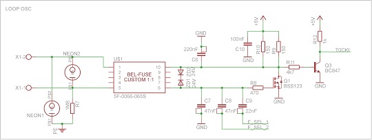
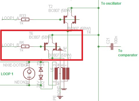
Vehicle loop detector circuit schematic.
The detector powers the loop causing a magnetic field in the loop area.
A base frequency is established when there is no vehicle over the loop.
Extension cable which in turn connects to the vehicle detector.
For high bed vehicle detection the typical loop size is 6 x 8.
Observe the detection call light on the detector module for all sensitivity settings.
View more loop detector loop overview.
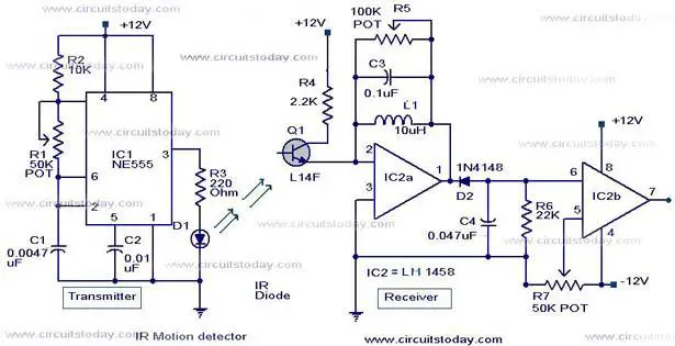
Loop detector schematic modified to drive a relay.
We carry models from emx platinum access northstar diabo mmtc liftmaster doorking reno a7e.
This circuit can also be used in conjunction with my delay.
The microcomputer monitors the oscillator frequency and controls the switching of the capacitors to periodically return the frequency to a predetermined value.
A circuit used to detect a vehicle on blacktop pavement concrete and trigger an alarm or relay.
Detection distance is much better with a large 6 foot coil.
Drive a large vehicle over adjacent lanes loop detectors and observe if a false call spillover is detected.
The octal connector is available as a harness or a mountable socket.
The number of turns in the loop is determined by the size of the loop.
Into the designated loop.
Good practice dictates multiple loops and detectors in this situation.
If the inductive loop is placed correctly it will detect vehicle open gate and keep it open until the vehicle clears the gate.
An induction loop vehicle detector comprises an oscillator circuit having a plurality of capacitors switchable in circuit with a road loop under the control of a microcomputer to determine the oscillator frequency.
For example a 4 x 8 loop will give a detection height between 2 1 2 and 2 3 4 feet.
Set the sensitivity to the lowest setting that will detect a bicycle.
Executive summary of the induction loop vehicle detector.